
Optical systems in industrial manufacturing environments operate under constraints that consumer-grade imaging components cannot accommodate. The specification, selection, and integration of Industrial Lenses For Its intended use cases demand an engineering approach that accounts for spectral range, mechanical tolerances, and environmental stability. This article examines the technical foundations of industrial optics, performance metrics that define suitability for specific tasks, and the practical considerations that separate functional systems from optimized production tools.
Technical Specifications and Performance Criteria
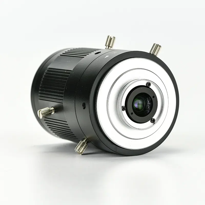
The optical performance of any industrial lens is defined by measurable parameters that directly influence inspection reliability and measurement accuracy. Resolution, distortion characteristics, and spectral transmission form the foundational triad of specification criteria. For applications requiring sub-pixel edge detection, the modulation transfer function (MTF) provides a more meaningful metric than simple resolution figures, as it describes contrast retention across spatial frequencies.
Resolution and Pixel Pitch Matching
Sensor resolution continues to advance, with 12-megapixel and 20-megapixel detectors becoming standard in high-end inspection systems. The optical system must resolve detail at the pixel level while maintaining contrast above 30% at the Nyquist frequency. Industrial Lenses For Its intended use with specific pixel pitches require careful selection of focal length and aperture to achieve the desired field of view without sacrificing edge sharpness. A lens that resolves 160 line pairs per millimeter at center may drop to 80 lp/mm at the corners, which becomes significant when inspecting large components where edge features carry critical dimensional data.
Distortion Control and Measurement Accuracy
Geometric distortion in machine vision applications directly impacts measurement repeatability. For dimensional metrology, distortion coefficients below 0.05% are expected from precision optics. Telecentric designs offer near-zero distortion but come with size and cost constraints that make them suitable primarily for high-precision gauging applications. Industrial Lenses For Its specific use in measurement tasks must provide distortion characterization data, not just maximum values. The distortion curve shape matters more than the peak value, as non-monotonic distortion patterns cannot be fully corrected through software calibration.
Aperture and Depth of Field Trade-offs
Working aperture selection involves balancing light throughput against depth of field and diffraction limitations. A lens set to f/2.8 delivers maximum resolution but restricts the depth of field to a few millimeters at short working distances. Closing to f/8 extends the in-focus range but introduces diffraction softening that reduces effective resolution. Industrial Lenses For Its role in production line inspection often requires f/4 to f/5.6 as a practical compromise, though variable aperture mechanisms allow adjustment for different inspection tasks without changing the optical assembly.
Application Environments and Optical Demands
Industrial settings present environmental challenges that consumer optics never encounter. Temperature fluctuations, vibration, and airborne particulates all affect optical performance over time. Understanding these environmental factors is essential for specifying optics that maintain calibration over months of continuous operation.
High-Temperature Production Zones
Glass processing, metal forming, and semiconductor manufacturing often position inspection optics near heat sources. Standard optical adhesives degrade above 80°C, causing element decentering and focus drift. Industrial Lenses For Its deployment in high-temperature zones requires thermally stabilized mechanical housings and adhesives rated for 120°C continuous operation. Athermalized designs that compensate for thermal expansion through selected glass types and housing materials maintain focus across a 60°C temperature range without manual adjustment.
Vibration-Prone Mounting Positions
Robotic inspection stations and production lines with high-speed indexing create vibration profiles that affect image sharpness. Lens mounts with locking mechanisms and reinforced barrels resist resonant vibration modes that would blur images in standard cinematography lenses. Industrial Lenses For Its application on articulated arms benefits from lightweight materials that reduce inertial loading while maintaining optical alignment through multiple axes of motion.
Dust and Contaminant Management
Optical surfaces exposed to production environments accumulate contaminants that scatter light and reduce contrast. Sealed lens assemblies with nitrogen purging or IP67-rated housings prevent particle ingress. For Industrial Lenses For Its intended use in food processing or pharmaceutical inspection, cleanroom-compatible surfaces and materials that resist chemical cleaning agents become necessary specifications.
Customization Parameters for Specific Tasks
Standard catalog lenses serve a broad range of applications but rarely match the exact requirements of a specific inspection station. Custom optical designs address unique constraints related to working distance, spectral range, and physical envelope. Customization decisions involve trade-offs between optical performance, cost, and delivery timeline.
Spectral Band Optimization
Standard machine vision lenses correct for visible wavelengths between 400 and 700 nanometers. Applications using infrared illumination for plastic sorting or ultraviolet excitation for fluorescence inspection require spectral coatings and glass types that transmit beyond the visible range. Industrial Lenses For Its specific spectral band may incorporate AR coatings optimized for 850 nanometer near-infrared or fused silica elements for deep UV transmission above 80% at 266 nanometers.
Mechanical Interface and Mounting
While C-mount remains prevalent for sensors up to 2/3 inch, larger sensors require F-mount or M42 interfaces to avoid vignetting. Custom flanges and adapter rings enable integration with non-standard camera housings without compromising back focal distance. Industrial Lenses For Its mounting configuration must account for the exact flange focal distance of the intended camera to maintain infinity focus capability.
Focus and Iris Actuation
Manual focus and iris adjustment serve prototyping well but become liabilities in automated production. Motorized focus and iris mechanisms integrated into the lens barrel allow remote control through the vision system software. Lockable set screws prevent accidental adjustment in applications where settings remain fixed for months. Industrial Lenses For Its automation integration often involves custom firmware that reports lens position and temperature to the central control system.
Integration and Calibration Workflows
Deploying new optics into a production line involves procedures that ensure the system performs to specified tolerances. Calibration targets, alignment fixtures, and verification protocols form the practical workflow that validates optical performance under actual operating conditions.
Initial Alignment Procedures
Mechanical alignment of the lens to the camera sensor axis requires precision shims or adjustable mounts that provide pitch, yaw, and roll adjustments. Collimated light sources and alignment targets simplify the centering process. A poorly aligned lens introduces asymmetric distortion and reduces effective resolution more than the lens specifications suggest. Jinyuan supplies alignment targets and calibration documentation with each optical assembly to expedite this process.
Distortion Calibration
Software calibration corrects residual distortion but requires accurate distortion maps. Grid targets with known geometry provide the calibration data necessary to generate correction coefficients. For high-accuracy measurement, calibration at multiple working distances accounts for perspective effects that change with object position. Industrial Lenses For Its calibration data must remain accessible for scheduled recalibration intervals to compensate for thermal drift and mechanical settling.
Illumination Integration
Lens performance depends on the illumination spectrum and geometry. Coaxial illumination introduces reflections that reduce contrast, while darkfield illumination enhances surface defects. The optical system, illumination source, and object surface finish form a triangular relationship that determines inspection success. Testing Industrial Lenses For Its intended illumination configuration during system qualification prevents surprises during production ramp-up.
Performance Verification Methods
Regular verification of optical performance ensures the inspection system maintains its specified capability. Standardized test targets and automated analysis routines provide quantitative metrics that indicate when maintenance or replacement is necessary.
Resolution Testing with USAF Targets
The USAF 1951 resolution target provides a quick visual assessment of resolving power. Automated analysis compares captured images to stored reference patterns, detecting degradation in contrast transfer at specific spatial frequencies. A resolution loss of 20% often precedes observable image degradation, providing early warning of optical contamination or misalignment.
Contrast Transfer Function Measurement
Slanted-edge analysis methods measure contrast transfer across the entire field of view. Software calculates the MTF at multiple positions, generating a map that identifies localized performance issues. This technique catches element decentering, tilt, or localized surface damage that resolution targets alone would miss. For Industrial Lenses For Its use in critical measurement applications, MTF measurement forms part of the ongoing quality assurance plan.
Distortion Verification Using Dot Grids
Re-measuring distortion coefficients at scheduled intervals detects mechanical shifts in the optical assembly. A change in distortion of 0.02% indicates possible lens element movement or mount deformation. This verification requires consistent target placement and fixturing to avoid introducing measurement errors that mask actual optical changes.
Frequently Asked Questions
How do I determine the correct focal length for my inspection task?
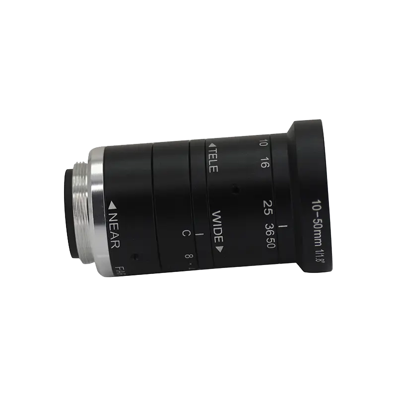
Determine the required field of view and working distance first. The focal length calculation divides the sensor width multiplied by the working distance by the field of view width. For a 2/3-inch sensor with 8.8 mm width, a 200 mm working distance, and a 100 mm field of view, the required focal length is 17.6 mm. Available focal lengths near this calculated value provide the starting point for selection.
What causes inconsistent edge sharpness across the image field?
Edge sharpness variations typically result from sensor tilt relative to the lens optical axis, field curvature in the lens design, or decentered lens elements. Check the mechanical alignment first, as tilt produces asymmetric edge blur that varies with focus. If alignment is correct, examine the MTF curves for field curvature, which shows as different optimal focus positions between center and edge.
When should telecentric lenses be used instead of conventional designs?
Telecentric lenses provide constant magnification across the working depth range, making them essential for measuring parts with varying thickness or for inspecting components that vibrate along the optical axis. Conventional lenses change magnification with distance, introducing measurement errors that exceed acceptable limits for tolerances below 50 microns.
How does sensor pixel size affect lens selection?
The lens must resolve detail at the pixel level. For a sensor with 5-micron pixels, the lens should deliver at least 100 line pairs per millimeter at 50% MTF. Smaller pixels require higher resolution from the lens, often pushing into diffraction limits at larger apertures. Matching lens resolution to pixel pitch prevents the lens from becoming the resolution bottleneck in the imaging chain.
What maintenance schedule protects optical performance over time?
Visual inspection of optical surfaces at weekly intervals catches contamination before it affects performance. Clean the external surfaces monthly using optical-grade wipes and solvents. Verify resolution and distortion quarterly using test targets. Replace protective windows or cover glass annually, or immediately if scratches appear in the imaging area. Jinyuan provides maintenance kits and verification targets with each system to support consistent care.
Can a single lens design serve multiple inspection stations?
Identical lens designs can serve multiple stations, but each station requires independent verification of optical performance due to variations in camera alignment, illumination, and environmental conditions. Standardizing on a single design simplifies spare parts management and training, but each lens must pass the same verification protocol before deployment.
What impact does aperture selection have on measurement repeatability?
Smaller apertures increase depth of field but introduce diffraction blur that reduces edge contrast, making edge detection less repeatable. A larger aperture improves edge contrast for sharp features but reduces depth of field, causing focus variations to affect measurement results. Test edge detection repeatability at multiple apertures to find the setting that balances depth of field and contrast for your specific features.
For applications requiring specific optical designs, environmental hardening, or specialized coatings, Jinyuan offers engineering consultation and custom optical assemblies to meet production demands. The selection and integration of Industrial Lenses For Its intended use should be based on thorough analysis of the inspection requirements, environmental factors, and performance validation protocols to achieve reliable, repeatable results in production environments.
For inquiries regarding custom optical specifications, performance testing, or integration support, contact the engineering team at Jinyuan with your application parameters to begin the specification process for your inspection system requirements.