
Micro-optics now drive innovation across industries where space is at a premium. Medical endoscopes, wearable AR displays, miniature drone sensors, and compact machine vision modules all demand optics that occupy fractions of a cubic centimeter. Standard catalog lenses cannot solve these problems. They take up too much space, weigh down sensitive hardware, and fail to meet unique spatial envelopes.
Engineering teams must design custom optics that blend directly into the host device. A true Compact Appearance Lens is not simply a standard lens scaled down. It is an integrated optomechanical assembly that balances physical boundaries with diffraction limits, thermal swings, and assembly constraints. At Jinyuan, our engineering group works directly with product developers to turn aggressive form-factor sketches into mass-producible micro-optical products.
Planning a new embedded vision project? Submit your preliminary lens drawings or RFQ to our engineering department for an immediate design for manufacturing (DFM) evaluation.
What Defines a Compact Appearance Lens in Modern Systems?
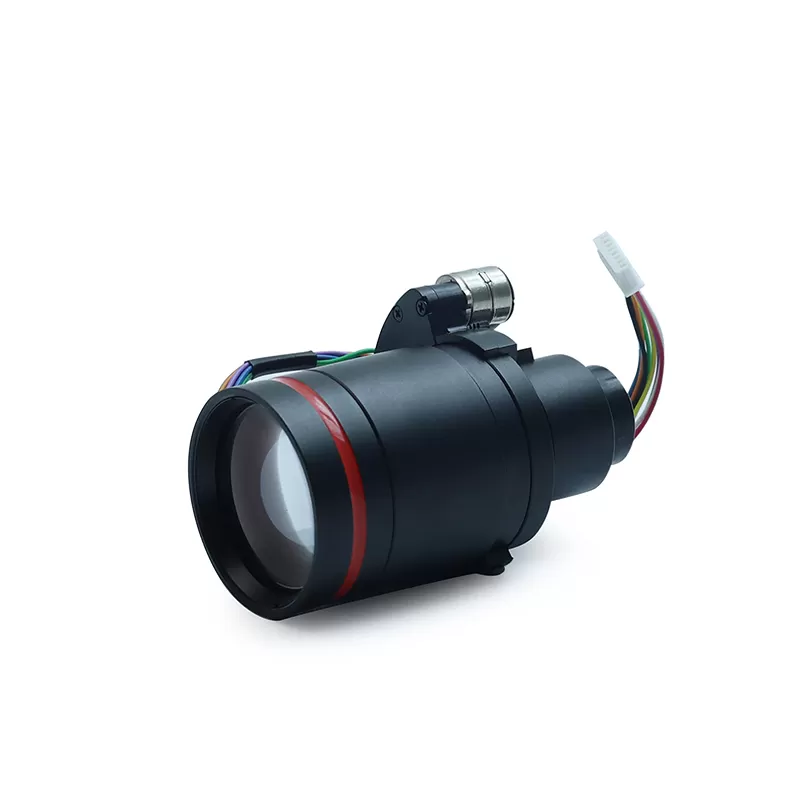
A Compact Appearance Lens features a clean, minimalist mechanical housing designed for flush-mounting, hidden-aperture placement, or direct insertion into narrow enclosures. In handheld medical devices or discreet inspection cameras, protruding barrels and bulky retaining rings compromise industrial design and mechanical durability.
Designing this class of lens requires solving a tough paradox: how to deliver crisp images and wide angles while cutting total track length and external diameter to the bare minimum. Below are the five technical factors you must address to succeed.
1. Form Factor & Optical Architecture Constraints
The physical envelope dictates every optical decision from the initial ray-tracing phase. When working within strict physical limits, optical designers must balance three tightly linked parameters: Total Track Length (TTL), Field of View (FOV), and target image circle.
TTL vs. Optical Path Management
Total Track Length is the distance from the front vertex of the first lens element to the image sensor plane. Shrinking TTL while preserving a wide field of view increases the optical power of individual elements. This steepens surface curvatures and intensifies field curvature.
- Folded Optics: When axial depth is heavily restricted, introducing a 90-degree folding prism or mirror redirects the optical path along the device's length or width, maintaining a flat external profile.
- Freeform Optical Surfaces: Symmetrical spherical or aspherical geometries sometimes fail to correct off-axis aberrations in compressed spaces. Freeform surfaces break rotational symmetry, allowing a single element to do the work of two or three traditional lenses.
Sensor Pairing and Chief Ray Angle (CRA) Matching
Modern micro-sensors (such as 1/6-inch or smaller formats) feature tiny pixels, often below 1.4 microns. These micro-pixels use micro-lenses on their surfaces that accept light only within a specific Chief Ray Angle (CRA) profile. If your micro-optics design produces a lens CRA that deviates more than 2 to 3 degrees from the sensor manufacturer's CRA, your images will show severe corner shading, color shifts, and vignetting.
2. Optical Performance vs. Miniaturization
Miniaturization forces optical physics to its absolute edge. As elements shrink, the aperture stop contracts. Smaller physical apertures drop your system straight into the diffraction-limited zone, where Airy discs broaden and reduce image contrast.
MTF and Resolution Limits
Modulation Transfer Function (MTF) quantifies optical contrast at specific spatial frequencies (line pairs per millimeter). When designing a Compact Appearance Lens, designers must calculate whether spatial frequency targets match the Nyquist limit of small-pitch sensors. Pushing for high center resolution often causes edge-of-field resolution to fall off rapidly unless you introduce specialized aspheric corrections.
Aberration and Distortion Correction
A typical full-sized camera objective uses six to eight elements to cancel out aberrations. A compact appearance micro-lens usually allows space for only two to four elements. Designers must use high-order aspheres to manage:
- Spherical Aberration: Correcting marginal rays that focus closer to the lens than paraxial rays.
- Chromatic Aberration: Pairing positive and negative lenses of differing dispersion to align red, green, and blue focal points.
- Geometric Distortion: Keeping barrel or pincushion distortion below 1% to 2% through optical means, or balancing it for digital calibration down the signal chain.
Stray Light and Flare Control
Internal reflections are harder to suppress inside tiny barrels. Light bounces off element edges and inner mechanical walls, flooding the sensor with glare. Micro-aperture baffles, black-flocking coatings along element rims, and wide-band Anti-Reflective (AR) coatings applied via physical vapor deposition (PVD) are mandatory steps to preserve contrast.
3. Advanced Material Selection & Thermal Stability
Choosing between optical glass, engineered polymers, or hybrid configurations determines whether your design survives production and real-world use. Compact designs provide almost no space for passive mechanical focus rings, making thermal stability critical.
Optical Plastics vs. Precision Glass
Optical polymers like Cyclic Olefin Copolymers (COC), Cyclo Olefin Polymers (COP), and optical-grade PMMA or polycarbonate dominate lightweight, high-volume production. They allow direct injection molding of complex aspheric profiles and integral alignment flanges. However, plastics have higher thermal expansion rates and lower scratch resistance.
Precision molded glass or wafer-level glass elements, by contrast, offer exceptional transmission, higher refractive indices, and robust environmental resilience. In medical devices undergoing repeated autoclave cycles, glass remains the only viable choice. Jinyuan regularly implements hybrid glass-plastic architectures to balance optical power, cost targets, and thermal durability.
Optical Athermalization Strategies
Enclosed micro-optics sit close to heat-generating components such as image signal processors, batteries, or LED illumination rings. When internal temperatures swing from -20°C to 60°C, the refractive index of plastic changes drastically (a high dn/dT coefficient), causing focus drift. Athermal design pairs plastic lenses with negative dn/dT values alongside specific optical glass elements and carefully chosen barrel materials (such as aluminum, brass, or engineered PEEK) to keep the focal plane pinned to the sensor plane across the entire temperature range.
4. DFM & Micron-Level Tolerancing
A brilliant optical design on a computer screen is useless if a precision shop cannot build it with repeatable yields. In conventional lenses, mechanical tolerances sit comfortably in the 10 to 20-micron window. In a Compact Appearance Lens, decentration or tilt tolerances often drop to 1 to 3 microns.
The Realities of Micro-Assembly
As lens diameters dip below 5 mm, minor assembly errors lead to severe image defects. A tilt of just 0.05 degrees on a high-curvature asphere can destroy one side of your image plane while keeping the other sharp. Designers must run thorough Monte Carlo tolerance analyses early, balancing nominal performance against real-world shop-floor tolerances.
Manufacturing Methods: SPDT vs. Wafer-Level Optics
The manufacturing process influences both your budget and timeline:
- Single Point Diamond Turning (SPDT): Ideal for rapid prototyping and low-to-medium batch runs. SPDT cuts optical molds and prototype parts with sub-nanometer surface roughness.
- Precision Injection Molding: The standard for high-volume consumer and diagnostic optics. Tooling requires extreme precision, but individual parts become very cost-effective.
- Wafer-Level Optics (WLO): Lenses are molded in arrays on
glass wafers, stacked, bonded, and then diced into thousands of individual
optical blocks. WLO delivers unmatched miniaturization and automated alignment,
making it the premier choice for ultra-compact footprints.
5. Exterior Integration & Robust Packaging
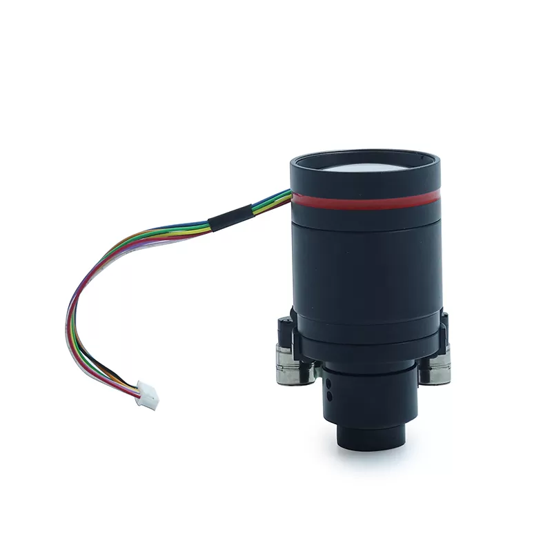
The optical barrel does more than hold the glass—it serves as the structural and aesthetic interface to the finished device. The exterior geometry of a Compact Appearance Lens dictates whether your product achieves an IP-rated barrier or a seamless front plate.
Flush-Mount and Bezel Integration
Micro-optics often require flush mounting to smooth out surgical tools, prevent debris collection on drone hulls, or keep consumer electronics sleek. Lens barrels require integrated mounting shoulders, precision threads, or locating pins that register directly with the host chassis. The outer element should sit flush with the surrounding bezel to avoid dirt traps and simplify cleaning.
Sealing, Potting, and Coatings
Environmental sealing protects sensitive internal elements from catastrophic failure:
- Adhesive Gaskets and UV Curing: Optical-grade, low-outgassing UV epoxies seal lens elements against moisture and dust ingress, easily satisfying IP67 or IP68 criteria.
- Hard Protective Coatings: Diamond-Like Carbon (DLC) coatings on the exposed front surface resist heavy abrasion, chemical exposure, and aggressive cleaning solvents.
- Hydrophobic and Oleophobic Coatings: Anti-smudge (AF/AS) topcoats repel water, fingerprints, and biological fluids, ensuring clear vision in challenging working environments.
Frequently Asked Questions
Q1: What is the main difference between a standard micro-lens and a Compact Appearance Lens?
A1: While both share miniature dimensions, a standard micro-lens typically prioritizes standalone optical specs inside a standard cylindrical barrel. A Compact Appearance Lens is designed from the start to integrate directly with host product mechanics. It features ultra-short track lengths, flush-mountable interfaces, clean industrial packaging, and hidden aperture options suited for high-end consumer and medical hardware.
Q2: How small can a custom Compact Appearance Lens be manufactured?
A2: Production limits depend on optical performance targets and sensor size. Using Wafer-Level Optics (WLO), complete multi-element modules can be manufactured with footprints as small as 1.0 mm x 1.0 mm and total track lengths well under 2.0 mm, commonly seen in single-use medical endoscopes.
Q3: Can plastic optics withstand medical sterilization procedures?
A3: Standard optical plastics cannot survive standard steam autoclaving (134°C). However, specialized optical polymers can tolerate Ethylene Oxide (EtO) sterilization and gamma radiation. For repeated autoclave cycles, designers must specify all-glass optical elements seated inside stainless steel or titanium housings.
Q4: Why does my micro-lens design lose contrast toward the image edges?
A4: Edge contrast loss usually stems from a mismatch between the lens Chief Ray Angle (CRA) and the sensor CRA, steep field curvature, or off-axis astigmatism. Addressing this requires re-optimizing the final aspheric surfaces and adding internal micro-baffles to suppress peripheral ray flare.
Q5: What initial information is needed to start a custom lens design?
A5: You should provide target sensor specifications (pixel size, active area, CRA), available mechanical envelope (maximum diameter, TTL), target Field of View, working distance, operating temperature limits, and target production volume.
Build Your Custom Micro-Optics with Jinyuan
Designing a high-yield, miniature optical system requires deep collaboration across optical physics, mechanical engineering, and micro-fabrication. Balancing physical boundaries, optical resolution, material stability, and clean packaging is essential for building a successful product.
At Jinyuan, we help equipment manufacturers turn ambitious optical ideas into production-ready assemblies. Whether you need a proof-of-concept prototype built via diamond turning or high-volume production for commercial rollout, our engineers provide the hands-on design support and manufacturing oversight your project demands.
Ready to start your micro-optics project? Contact Jinyuan today to consult with our optical engineering team and receive a comprehensive DFM assessment and quotation for your custom design.